Login / Register

Verify OTP

Update Profile

What Are Carbide Inserts? A Complete Beginner’s Guide
Carbide inserts are replaceable cutting tips used in CNC machining for turning and milling. This beginner’s guide explains their ISO nomenclature, shapes, coatings, and applications across industries like automotive, aerospace, and die & mold. Learn how to read codes like CNMG 120408 and choose the right insert for your job.
Carbide inserts are the tiny, replaceable cutting tips that do the heavy lifting in metal cutting. They sit in a toolholder on a CNC lathe or mill, shear metal at incredible speeds, and can be rotated (“indexed”) to a fresh edge when worn. Understanding insert codes, chipbreakers, grades, and coatings will save money, improve surface finish, and reduce downtime—whether you’re in automotive, aerospace, die & mold, or general job-shop work.
What Are Carbide Inserts?
Carbide inserts are replaceable cutting tips made primarily from tungsten carbide, a material harder than steel and resistant to wear and heat. Unlike traditional solid cutting tools, inserts can be clamped onto tool holders, allowing for fast replacement without regrinding the entire tool.
Benefits of Carbide Inserts
- High cutting speed capability
- Longer tool life than High-Speed Steel (HSS)
- Improved surface finish
- Reduced downtime due to easy replacement
Applications: Turning, milling, drilling, and grooving operations in metals ranging from aluminum to hardened steel.
Understanding ISO Carbide Insert Nomenclature
ISO 1832 defines a standardized code for carbide inserts, helping machinists identify shape, clearance, tolerance, chip breaker, and coating at a glance.
Example: CNMG 120408
| Code | Meaning |
|---|---|
| C | 80° diamond shape |
| N | 0° clearance angle (neutral) |
| M | Medium tolerance |
| G | Ground insert |
| 120408 | Insert dimensions: 12 mm inscribed circle, 4 mm thickness, 8 mm cutting edge length |
By reading ISO codes, you can quickly select the right insert for a specific material and operation.
Carbide Insert Features Explained
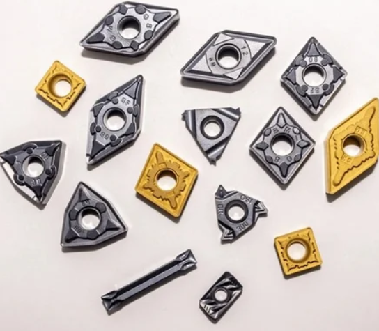
1. Shape
- Common shapes include C (diamond), D (55° diamond), T (triangle), R (round). Shape affects strength, clearance, and chip flow.
2. Clearance Angle
- Defines the angle between the insert and workpiece. Neutral, positive, and negative angles influence cutting forces and surface finish.
3. Tolerance
- Indicates dimensional accuracy. Medium tolerance (M) is standard for general machining, while tight tolerance (P) is for precision work.
4. Chip Breaker
- A groove or indentation that controls chip formation, preventing long, tangled chips that can damage tools or workpieces. Different designs suit materials like steel, cast iron, or aluminum.
5. Coating
- PVD (Physical Vapor Deposition): Thin, hard coating for general machining at higher speeds.
- CVD (Chemical Vapor Deposition): Thicker coating, excellent for heavy-duty cutting.
Coatings increase wear resistance, reduce friction, and improve heat dissipation.
Types of Carbide Inserts
- Turning Inserts: Used on lathes for shaping cylindrical parts.
- Milling Inserts: Used on milling cutters for flat or contoured surfaces.
- Grooving & Threading Inserts: Specialized for cutting grooves, slots, or threads.
Practical Applications Across Industries
-
Automotive: Engine components, shafts, and gears.
-
Aerospace: Titanium and nickel alloys requiring high-speed precision machining.
-
Die & Mold: Tooling and molds requiring excellent surface finish.
-
General Machining: Stainless steel, carbon steel, aluminum parts.
By selecting the correct ISO insert type and coating, manufacturers improve productivity and reduce costs.
How to Choose the Right Carbide Insert
-
Identify material to machine
-
Determine cutting operation (turning, milling, grooving)
-
Check ISO code for shape, clearance, and tolerance
-
Select chip breaker suitable for material
-
Choose coating based on speed, feed, and material hardness
Tip: CNC Tools Depot stocks all leading brands, making it easy to find the perfect match.
Conclusion
Carbide inserts are the backbone of modern CNC machining, offering precision, durability, and versatility across industries. Understanding ISO codes, chip breakers, and coatings ensures optimal performance and longer tool life.
Explore CNC Tools Depot’s marketplace to browse top-quality carbide inserts from leading brands and elevate your machining capabilities.
Brand comparison
- Sandvik: Wide range of PVD/CVD inserts for high-speed operations.
- Kennametal: Known for tough inserts for stainless steel and aerospace alloys.
- Iscar: Innovative chip breaker designs for complex applications.
Frequently Asked Questions
C = 80° diamond shape; N = 0° clearance (negative); M = medium tolerance; G = type with hole, typically double-sided geometry. Numbers give size, thickness, and nose radius (e.g., 12 = 12 mm edge length, 04 = 4.76 mm thick, 08 = 0.8 mm radius)
Same positions: C (shape), C (7° positive clearance), M (tolerance), T (single-sided type with double countersink). Numbers: 06 size, 02 thickness code, 04 nose radius (0.4 mm). Always confirm in the code charts.
Start with PVD-coated, sharp-edge grades and positive geometries to reduce built-up edge; choose the brand’s M-group recommendation (e.g., -PM style). Fine-tune with speeds/feeds per the catalog.
CVD handles high heat/wear and shines in stable roughing of steels and irons. PVD allows sharper edges and excels in stainless, superalloys, and finishing.
Core ISO logic persists, but milling adds stations for edge prep and cutting direction in some catalogs; the 4th station still indicates geometry/clamping.
That’s the chipbreaker/geometry (-PM) and grade (4325). The base code is standardized; the suffixes are brand-specific for application tuning.
In turning we commonly say chipbreaker; in milling, the rake face is often discussed as a chipformer—the function is similar (chip control) but milling is an interrupted cut

India's Largest Marketplace for Carbide Inserts & Cutting Tools.
© 2026. All Rights Reserved
Disclaimer: All Brand Logos belong to their respective owners, CNC Tools Depot is sharing publicly available information