Login / Register

Verify OTP

Update Profile

Turning inserts, often identified by ISO 1832 codes such as CNMG or DNMG, are optimized for continuous single-point cutting operations on lathes. Their geometry, chipbreaker design, clearance angles, and coatings are tailored to ensure stability and long wear resistance during turning. In contrast, milling inserts—like APKT or SNMG—are built for multi-edge engagement in high-speed milling cutters, designed to withstand interrupted cuts and higher impact forces.
Turning vs. Milling Inserts: What’s the Difference?
Understanding the difference between turning inserts and milling inserts helps you pick the right carbide inserts for every job, reduce cycle time, and extend tool life. This guide explains the geometry, ISO 1832 nomenclature, coatings (PVD vs CVD), chipbreakers, and practical selection tips for CNC cutting tools — with examples and brand-neutral advice.
why this matters
On a modern shop floor, the right carbide insert choice can be the difference between predictable multi-shift tool life and constant rework. Turning inserts and milling inserts are both indexable carbide tips, but they are engineered differently because turning (lathe) and milling (cutter) impose different forces, chip flow, and clamping constraints. Choosing the correct insert family, geometry and grade reduces wear, improves surface finish and lowers cost-per-part.
Differences
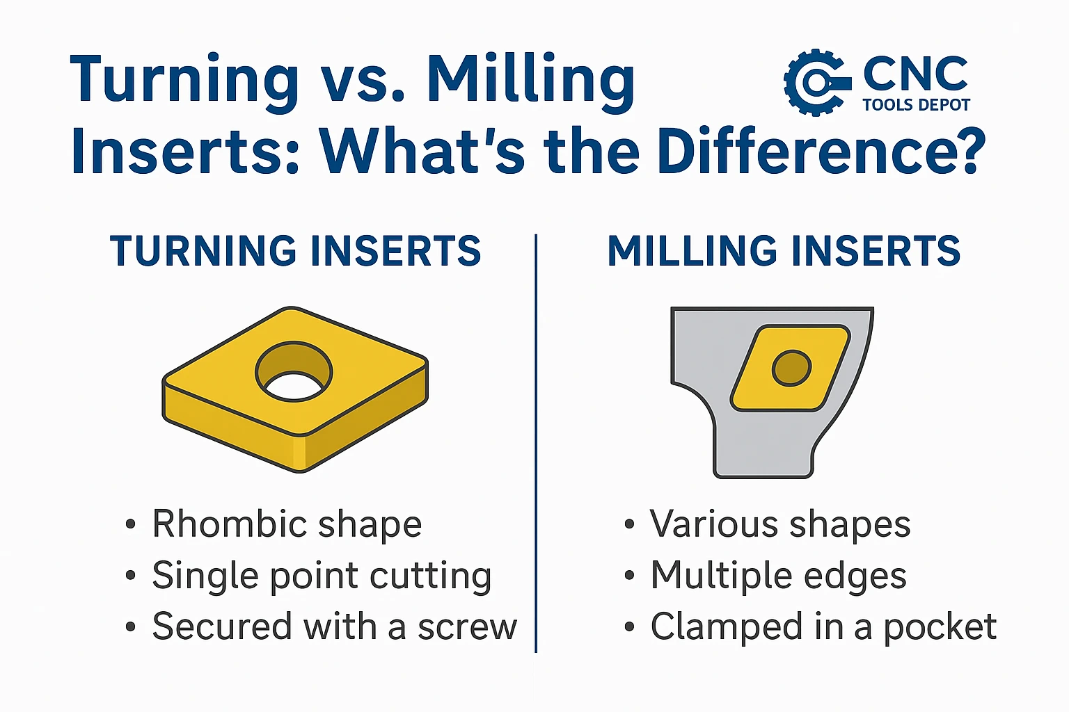
Turning inserts (typical characteristics)
- Geometry: often rhombic, triangular or square shapes with a hole for secure clamping; designed for single-point or multi-edge turning holders.
- Relief/clearance: ISO codes allow “negative” (0°) and positive relief options — negative inserts (0°) are stronger for heavy cuts; positive relief are sharper and cut easier for finishing.
- Edge use: many turning inserts are double- or multi-sided (indexed) to maximize edge count.
Milling inserts (typical characteristics)
- Geometry: come in a wider variety (round, square, triangular, wavy, step-style) to fit different cutter bodies; edge exposure and mounting must resist centrifugal and bending loads.
- Mounting: clamped into a pocket on a rotating cutter (face, shell or end mills) where balance, seat fit and screw torque are critical.
- Multi-edge & chip-splitting: many milling inserts are designed with chip-splitters and wiper edges to tolerate higher feedrates and intermittent cutting.
ISO 1832
ISO 1832 standardizes an insert designation so you can order the exact geometry (shape, clearance, tolerance, size, thickness, nose radius). The code format differs slightly for turning vs milling but the idea is the same: letters first (shape, relief, tolerance) then numbers for size and radius.
Turning example — decode CNMG 120408
- C = 80° rhombic (shape).
- N = 0° clearance (negative insert).
- M = tolerance / designation (medium class in this position for turning).
- G = profile/type (often indicates ground planar cutting edge or chipbreaker family per manufacturer).
- 12 = inscribed circle (IC) size ≈ 12.7 mm.
- 04 = thickness code (≈ 4.76 mm).
- 08 = nose radius 0.8 mm.
This ISO-style breakdown is documented in the ISO 1832 designation key and manufacturer designation tables.
Milling example — decode R390-17 04 04M-PM (typical form)
- R = round insert (shape used by many milling systems).
- 390 = body / cutter family (example: 90° cutter code, manufacturer-dependent sizing).
- 17 = insert width/other dimensional code.
- 04 = thickness (4.76 mm) and 04M may show corner radius or application range; PM can map to primary application (P = steel, M = medium machining).
Milling codes vary across manufacturers but are rooted in ISO geometry fields; always check the cutter maker’s nomenclature sheet for exact interpretation.
Practical tip: use the ISO code to match shape + clearance + size + radius — then consult the manufacturer datasheet to match the chipbreaker and grade (chipbreakers & coatings are not fully standardized in ISO).
Coatings & Grades
- PVD (Physical Vapor Deposition): thin, hard layers (TiN, TiCN, AlTiN variants) applied at lower temperatures. PVD coatings preserve a sharper edge and are excellent for finishing or materials where edge sharpness matters.
- CVD (Chemical Vapor Deposition): thicker, high-temperature coatings that give strong thermal and abrasion protection — often better for abrasive or high-speed roughing in cast iron or certain steels, but require a tougher substrate because of the high application temperature.
How that maps to turning vs milling: both operations use PVD and CVD grades, but milling (higher engagement, interrupted cuts) may favor tougher CVD or special multi-layer PVD grades for heavy duty roughing, while finishing passes (turning or milling) often take advantage of sharp PVD finishes and cermet options. Always match grade charts to your workpiece material and operation.
Chipbreakers & Edge prep
- Chipbreakers shape and break the chip so it doesn’t tangle, re-cut, or cause heat spots — crucial for both milling and turning. Effective chip control reduces crater wear and improves heat evacuation. Manufacturers provide chipbreaker maps keyed to feed and depth-of-cut.
- Edge prep / honing & T-lands: strengthen the cutting edge against micro-chipping and notch wear. Use a honed edge for interrupted cuts and a sharper edge for ultra-finish operations.
(Practical note: chipbreaker geometry is manufacturer-specific — ISO codes won’t tell you the exact chipbreaker shape, so always consult the maker’s product sheet.)
Step-by-step: choose the correct insert for your job
-
Identify operation & material: turning vs milling? steel, stainless, cast iron, aluminum, titanium? (ISO material categories: P, M, K, N, S, H).
-
Decode the ISO geometry you need: shape, clearance, IC, thickness, radius (use ISO 1832 key).
-
Select chipbreaker matched to feed & DOC: use the manufacturer’s chipbreaker map.
-
Pick coating/grade: PVD for finishing/sharp edges; CVD for abrasive/high-temperature roughing — verify the grade chart for the material.
-
Ensure correct toolholding & clamping: clean seat, correct torque, minimize runout/overhang for milling cutters; negative/positive seating for turning as needed. Improper clamping causes uneven wear and chipping.
-
Start with manufacturer recommended cutting data and log tool life to tune speeds/feeds.
Frequently Asked Questions
Turning inserts are optimized for lathe-style single-point cutting and often have shapes and relief angles that suit steady tool-to-workpiece contact; milling inserts are shaped and mounted to resist rotating cutter forces and usually include chip-splitting/wiper features for high feeds.
ISO 1832 breaks codes into shape → clearance/rake → tolerance/profile → IC/thickness → radius. For turning CNMG 120408 use the ISO key; for milling, consult the cutter maker’s ISO-style sheet. Walter and ISO 1832 are good reference keys.
For stainless, PVD-coated fine-grain carbides are often preferred to reduce built-up edge and keep a sharp edge for finishing; CVD is used where abrasion resistance and high temperatures dominate. Always follow manufacturer grade recommendations for the material.
Check clamping and seat fit, reduce overhang, choose an insert grade made for intermittent cuts (tougher substrate), use the recommended chipbreaker for your feed/DOC, and start at the manufacturer’s suggested speeds/feeds. Logging tool life will let you optimize faster.

India's Largest Marketplace for Carbide Inserts & Cutting Tools.
© 2026. All Rights Reserved
Disclaimer: All Brand Logos belong to their respective owners, CNC Tools Depot is sharing publicly available information