Login / Register

Verify OTP

Update Profile

ISO Carbide Insert Nomenclature Explained (With Examples)
"Learn how to read ISO carbide insert nomenclature with clear examples. Understand shapes, clearance angles, tolerances, chipbreakers, and coatings to choose the right CNC cutting tools for your application."
Carbide inserts are the replaceable cutting tips that make modern CNC turning and milling fast, repeatable and cost-effective. Reading the ISO insert code lets you order the exact geometry (shape, relief, tolerance, size, radius, chipbreaker and more) without guessing — which saves machine time, reduces scrap, and keeps production predictable. The international designation system is defined by ISO 1832, the authority on indexable-insert codes.
What Are ISO Carbide Inserts?
ISO carbide inserts are standardized cutting tools defined under ISO 1832. They are widely used in turning, milling, and drilling operations. Each insert is identified by a code that communicates its geometry and characteristics, helping machinists and engineers select the ideal tool without trial and error.
Key Advantages:
- Faster setup and tool selection
- Predictable performance across materials
- Compatibility across brands like Sandvik, Kennametal, Iscar, and Kyocera
Understanding ISO Carbide Insert Codes
ISO insert codes are typically a 7–10 character combination of letters and numbers. Let’s break down a common example:
CNMG 120408
| Code | Meaning |
|---|---|
| C | Insert shape (80° diamond) |
| N | Clearance angle (0° neutral) |
| M | Tolerance class (medium) |
| G | Type of insert (ground) |
| 12 | Cutting edge length (mm) |
| 04 | Insert thickness (mm) |
| 08 | Nose radius (mm) |
Step 1: Shape
The first letter denotes the insert shape:
- C: 80° diamond (common for turning)
- D: 55° diamond
- T: Triangle
- R: Round
Tip: Shape affects strength and cutting direction.
Step 2: Clearance Angle
The second letter shows the clearance angle:
- N: 0° (neutral)
- S: 15°
- E: 5°
A proper clearance angle reduces rubbing and improves surface finish.
Step 3: Tolerance
The third letter indicates tolerance:
- M: Medium
- H: High precision
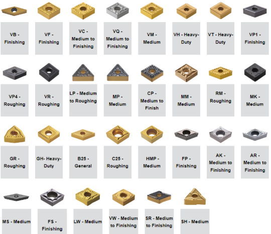
Step 4: Chip Breaker / Geometry
The fourth letter identifies chip control design and manufacturing method:
- G: Ground (precision)
- P: Pressed
- K: Special chip breaker
Tip: A good chip breaker prevents long stringy chips that can damage parts or machines.
Step 5: Size Designations
The numbers specify dimensions:
- 12 → edge length
- 04 → thickness
- 08 → nose radius
This helps select the insert according to the material, feed, and cutting depth.
PVD vs. CVD and Beyond
Carbide inserts often come with coatings that improve wear resistance, heat resistance, and tool life.
| Coating | Benefits | Ideal Use |
|---|---|---|
| PVD (Physical Vapor Deposition) | Thin, hard coating | High-speed steel, stainless steel |
| CVD (Chemical Vapor Deposition) | Thick, durable | Cast iron, hardened steel |
| TiN / TiAlN / AlTiN | Reduced friction & heat | High-speed machining & roughing |
Practical Applications Across Industries
-
Automotive: Engine components, shafts, and gear cutting
-
Aerospace: Titanium and aluminum alloys for structural parts
-
Die & Mold: Precise cavities and hardened tool steel
-
General Machining: Stainless steel, carbon steel, and non-ferrous metals
Conclusion
ISO carbide insert nomenclature may seem complex, but once decoded, it becomes an invaluable tool for CNC machinists and engineers. Knowing how to read insert codes ensures optimal tool selection, longer tool life, and higher-quality parts.
Explore CNC Tools Depot to browse a vast selection of ISO-compliant carbide inserts from top brands like Sandvik, Kennametal, Iscar, Kyocera, Mitsubishi, and more—your trusted source for precision CNC cutting tools.
Frequently Asked Questions
Read it left-to-right: C = 80° rhombic shape; N = 0° clearance (negative); M = tolerance (moulded); G = type/clamping & chipbreaker family. The numeric tail (e.g., 120408) gives size, thickness and radius. (See ISO 1832 and vendor datasheets for the exact numeric conversions.)
Inserts with PVD TiAlN/TiCN-type finishes and grades designed for stainless (higher edge stability and anti-smear behavior) are commonly recommended. Always pick a grade whose datasheet lists ISO-M (stainless) in its primary application.
Decode the first four letters (shape, clearance, tolerance, type), then the three numeric pairs (size/IC, thickness, radius). Use the manufacturer sheet for any suffix (chipbreaker/grade) after a dash.
CVD coatings are thicker and more wear-resistant (good for heavy steel machining). PVD coatings are thinner, applied at lower temperature, and keep a sharper edge (good for finishing and tricky materials). Choose by whether you need wear resistance (CVD) or sharpness/toughness at the edge (PVD).
Chipbreakers control chip shape and evacuation. The right chipbreaker reduces long chips, lowers vibration, and can improve surface finish — but the correct choice depends on feed, depth, material and coolant. Manufacturer chipbreaker charts show ap/f ranges.
CNC Tools Depot aggregates leading brands, offers detailed product specs for accurate ISO codes, and helps you match insert geometry, chipbreaker, and grade for your application — saving setup time and minimizing costly mistakes.

India's Largest Marketplace for Carbide Inserts & Cutting Tools.
© 2026. All Rights Reserved
Disclaimer: All Brand Logos belong to their respective owners, CNC Tools Depot is sharing publicly available information