Login / Register

Verify OTP

Update Profile

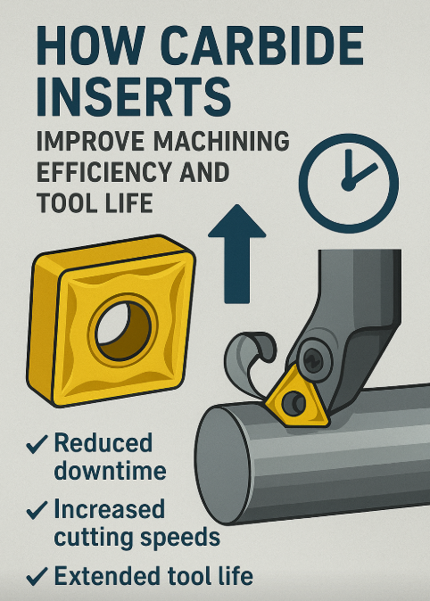
How Carbide Inserts Improve Machining Efficiency and Tool Life
Carbide inserts significantly boost machining efficiency by allowing higher cutting speeds, better chip control, and consistent surface finish. Their advanced coatings and optimized geometries reduce wear, minimize downtime, and extend tool life, making them essential for CNC turning and milling across industries like automotive, aerospace, and general machining.
n modern CNC cutting tools, carbide inserts are the unsung heroes that keep production moving: they reduce downtime, cut cycle time, improve surface finish, and — when selected correctly — dramatically extend tool life. For manufacturers from job-shops to aerospace lines, getting the right insert geometry, grade and coating is one of the highest-leverage decisions you can make. In this article we explain how carbide inserts deliver those gains, how to read ISO insert nomenclature, and practical tips to apply on the shop floor.
What is a carbide insert? (turning inserts, milling inserts, indexable tools)
Carbide inserts are small, replaceable cutting tips (usually cemented carbide) that mount in toolholders for turning, milling, drilling and threading. Because inserts are indexable (rotate/flip to a fresh edge), they let shops replace only the cutting tip — saving material, time and cost — rather than replacing an entire tool. Turning inserts and milling inserts share the same basic benefits but differ in shape, clamping and chipbreaker design to suit their operations.
How carbide inserts improve machining efficiency and tool life — the mechanics
-
Sharpened, engineered cutting edges — Carbide retains hardness at higher temperatures than HSS, so it cuts faster (higher cutting speed) with less wear.
-
Coatings (PVD, CVD, ceramic, AlTiN, TiN etc.) reduce friction and thermal damage at the cutting edge, slowing wear and preventing built-up edge. This increases tool life and maintains surface finish.
-
Geometry & chip control — Modern chipbreakers channel and break chips into manageable forms, reducing entanglement, improving heat evacuation and allowing higher metal removal rates. The right chipbreaker reduces vibrations and protects the cutting edge. Indexability and inventory efficiency — Indexable inserts allow quick edge changes and minimize setup downtime. When a corner wears, flip or index — no grind cycle required.
-
Tailored grades and application groups (P, M, K, N, S) — Carbide grades and coatings are engineered for material groups (e.g., P = steel, M = stainless/Ti, K = cast iron). Using the grade made for your material improves tool life and process stability.
Result: Higher cutting speeds, fewer tool changes, more predictable tool life, better surface finish and higher throughput.
ISO 1832 — How to read an insert code (step-by-step)
The international standard ISO 1832 defines the designation system for indexable inserts so buyers and engineers can specify geometry unambiguously. ISO
A typical turning example: CNMG 120408-M P5 (many suppliers use a very similar structure). Break it down:
Design group (letters): C N M G
C — Shape: 80° rhombic / diamond. (Common shapes: C = 80°, D = 55°, V = 35°, S = square, T = triangle.)
N — Clearance (relief) angle: N = 0° (negative insert). Other codes (C=7°, P=11°, etc.).
M — Tolerance / manufacturing: M typically denotes a molded tolerance class (medium/standard tolerance). Tighter tolerance options may be indicated by G (ground)
G — Cross-section / hole / style code: the fourth letter indicates cross-section type (presence of hole, countersinks, chipbreaker style). The combination defines how the insert clamps and which chipbreaker is present.
12 — Inscribed circle / cutting-edge length: often 12 = 12.7 mm (depends on shape).
04 — Thickness: typically 04 = 4.76 mm.
08 — Nose (corner) radius: 08 ≈ 0.8 mm.
Sandvik product pages show CNMG 12 04 08 mapping to IC ≈ 12.7 mm, thickness 4.76 mm and 0.7938 mm nose radius (≈0.8 mm).
Suffix / grade / chipbreaker (e.g., -M P5) — indicates chipbreaker geometry and grade/application field (P = steel, M = stainless/titanium, K = cast iron, etc.) and the manufacturer grade code. Chipbreaker codes specify whether the insert is for finishing, medium or roughing operations.
Short analogy: reading an ISO insert code is like reading a shoe tag — size (IC), sole type (cross-section), and whether it’s for running or hiking (chipbreaker/grade). Once you know each position, you can order exactly what you need.
Key technical features — what they mean to your process
1. Shape (first letter)
- What it affects: rigidity, number of cutting edges, access to profile/shoulder.
- Plain language: shape determines whether the insert is a workhorse (square) or a nimble profiler (small diamond).
2. Clearance (second letter)
- What it affects: cutting forces and tool clearance.
- Plain language: a positive clearance (e.g., 7°) gives a weaker but sharper edge (good for finishing). A 0° clearance (negative) is stronger for heavy cuts.
3. Tolerance / manufacturing class (third letter)
- What it affects: repeatability and fit in the toolholder.
G= ground (tighter tolerance),M= molded (standard). For high-precision work use ground inserts.
4. Cross-section / hole / chipbreaker style (fourth letter)
- What it affects: clamping method and chip control. Some codes signify a through-hole for clamping + a specific chipbreaker family; others are for screw-clamped or wedge clamping.
5. Chipbreaker
- Benefit in plain language: chipbreakers shape the chip so it doesn’t tangle around the tool or workpiece — like channels in a gutter guiding water away. The right chipbreaker reduces heat at the edge and prevents built-up edge (BUE).
6. Coating (PVD vs CVD)
- PVD coatings are thin and give a sharper edge and low friction — great for finishing and many general-purpose P applications.
- CVD coatings are thicker and form good thermal barriers (Al₂O₃ layers) — useful for heavy cuts and high temperature resistance in some operations. Choose coating by the material and cut type.
Step-by-step selection guide — improve efficiency & tool life
Use this practical checklist like a decision map:
-
Identify the workpiece material (ISO groups: P = steel, M = stainless/Ti, K = cast iron, N = non-ferrous, S = heat-resistant alloys). Match grade families. Pick shape & clearance — wide 80° (C/CNMG) for general turning; tighter angles for fine profiling. For heavy metal removal choose negative (0°) inserts. Choose chipbreaker for the cut — finishing vs medium vs roughing. If you need high MRR (metal removal rate), choose a roughing chipbreaker; for surface finish, choose finishing breaker.
-
Select grade & coating — e.g., for finishing steel use a PVD coated fine-grit grade; for interrupted cuts or high temp use a tougher CVD/Al₂O₃ backed gradePick nose radius & depth of cut — larger radius ≈ better support and higher feed but more cutting force; smaller radius = finer finishes at lower feed.
-
Set cutting parameters conservatively, then tune — use manufacturer recommendations (start ~70–80% of suggested for new setups), monitor wear, and adjust speed/feed for tool life or cycle time.
-
Index and log — when you index/replace, note life and conditions so you build a cutting database for repeatability.
Practical example: For medium finishing on alloy steel, a CNMG 120408 PVD-coated insert with a finishing chipbreaker (small nose radius, fine grade) gives good surface finish and long life if run at the recommended speeds and coolant practice.
Brand notes: Sandvik vs Kennametal vs Iscar (neutral comparison)
All follow ISO 1832 for geometry designations, so codes translate across brands — but each maker designs proprietary chipbreakers and grade names (so performance and recommended machining windows can differ). Sandvik publishes extensive grade guidance and tooling selection help. Kennametal provides insert ID systems and conversion/grade equivalence tools. Use manufacturer data sheets to choose the exact grade and chipbreaker family for your material and operation.
Industries and use cases
- Automotive: high throughput turning and milling for transmission, shafts and housings — prioritized MRR and consistent tool life.
- Aerospace: precision finishes on titanium and Inconel — tailored CBN/ceramic grades and strict chip control.
- Die & mold: fine finishes on hardened steels — small radii and specialized grades.
- General machining / job shops: broad range of CNMG, SNMG, DNMG geometries for flexible production. (Manufacturer catalogs provide application fields for each chipbreaker/grade.)
Conclusion — short summary & CTA
Carbide inserts are the backbone of efficient CNC cutting: carefully matching shape, clearance, tolerance, chipbreaker and coating — and reading the ISO code correctly — unlocks faster cycles, fewer tool changes, and longer tool life. Start with ISO 1832 decoding (e.g., CNMG 120408) and follow manufacturer grade/coating recommendations to tune your process. For trusted, cross-brand options and technical data sheets, explore CNC Tools Depot’s marketplace — compare Sandvik, Kennametal, Iscar, Korloy and others in one place to pick the perfect insert for your operation.
Explore inserts now at CNC Tools Depot — find the right CNMG, SNMG, TNMG and more for your job.
References / Recommended reading (trusted sources)
- ISO 1832:2017 — Indexable inserts for cutting tools — Designation. I
- Walter / industry ISO designation key (ISO 1832 mapping & chipbreaker fields).
- Sandvik Coromant — How to choose the correct turning insert (selection guidance).
- Sandvik Coromant — Cutting tool materials & coatings (PVD/CVD guidance).
- Sandvik product example: CNMG 12 04 08 product page (dimensions mappin
Frequently Asked Questions
CNMG breaks down as: C = 80° rhombic shape, N = 0° clearance (negative), M = tolerance/manufacturing class (medium/molded), G = cross-section/type code (hole/chipbreaker style). The numeric group (e.g., 120408) gives inscribed circle (12 → ~12.7 mm), thickness (04 → 4.76 mm) and nose radius (08 → ~0.8 mm).
For stainless (ISO group M) use grades and coatings made for low-ductility, high-work-hardening materials — typically PVD-coated, tougher grades with chipbreakers designed to avoid long, gummy chips. Check manufacturer application tables for the exact grade.
Split the code into the 4-letter design group (shape, clearance, tolerance, cross-section) and the 3-number dimension group (IC/edge length, thickness, nose radius). Suffixes give chipbreaker & grade. A simple cheat sheet or manufacturer insert chart is immensely helpful.
PVD = thin, low-friction coatings (sharper edges, good for finishing/general use). CVD = thicker coatings (Al₂O₃ layers) that act as thermal barriers for tougher or higher-temperature cutting. Choose based on cut type and work material. Sa
CNC Tools Depot aggregates trusted brands (Sandvik, Kennametal, Iscar, Korloy, etc.), lets you compare grades and chipbreakers side-by-side, and provides product data sheets so you can match ISO codes and application guidance before buying.

India's Largest Marketplace for Carbide Inserts & Cutting Tools.
© 2026. All Rights Reserved
Disclaimer: All Brand Logos belong to their respective owners, CNC Tools Depot is sharing publicly available information