Login / Register

Verify OTP

Update Profile

Different Types of Carbide Inserts and Their Applications
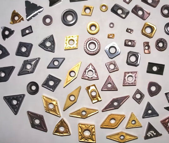
Carbide inserts are the replaceable cutting edges at the heart of modern CNC cutting tools. They let manufacturers change geometry, material grade and coatings without regrinding a whole tool — saving time, cost and improving process stability. From high-volume automotive production to one-off aerospace parts, the right insert geometry and grade can be the difference between a profitable run and scrap. Trusted technical resources and ISO standards (ISO 1832) make it possible to order and compare inserts precisely.
Carbide inserts are the replaceable cutting edges at the heart of modern CNC cutting tools. They let manufacturers change geometry, material grade and coatings without regrinding a whole tool — saving time, cost and improving process stability. From high-volume automotive production to one-off aerospace parts, the right insert geometry and grade can be the difference between a profitable run and scrap. Trusted technical resources and ISO standards (ISO 1832) make it possible to order and compare inserts precisely.
What Are Carbide Inserts?
Carbide inserts are replaceable cutting tips made of tungsten carbide, often coated for enhanced wear resistance. Unlike high-speed steel (HSS) tools, carbide inserts maintain sharpness at high speeds, making them ideal for high-volume production and hard materials.
Key Advantages
- High hardness and wear resistance
- Can operate at higher speeds
- Consistent cutting performance
- Versatile for turning, milling, and threading
ISO 1832
ISO 1832 defines a standardized code system to describe insert geometry, tolerance, chipbreaker, and coating. Reading these codes correctly helps you select the right insert for material and operation.
Example ISO Code: CNMG 120408
Let’s decode it step by step:
| Letter/Number | Meaning | Explanation |
|---|---|---|
| C | Shape | 80° diamond-shaped insert |
| N | Clearance angle | 0° clearance (neutral) |
| M | Tolerance | Medium tolerance |
| G | Type of insert | Ground insert |
| 12 | Size | Insert cutting edge length (mm) |
| 04 | Thickness | Insert thickness (mm) |
| 08 | Nose radius | Tip radius (mm) |
Tip: Always cross-reference ISO codes with manufacturer catalogs (Sandvik, Kennametal, Iscar) for brand-specific geometries.
Common Carbide Insert Shapes
Understanding shapes is crucial because it affects cutting angle, tool rigidity, and machining application:
- C – 80° Diamond: General-purpose turning, suitable for medium-to-heavy cuts.
- D – 55° Diamond: Ideal for finishing and narrow grooves.
- T – Triangle: High-strength insert for roughing operations.
- S – Square: Strong edge for heavy cuts and slotting.
- R – Round: Smooth contouring, reduces stress concentration.
Clearance Angle and Tolerance
1.Clearance Angle (N, P, R, L) defines how the insert avoids rubbing the workpiece.
- N (0°): Neutral, balanced cutting forces.
- P (+5°): Positive, reduces cutting forces, ideal for soft materials.
- R (-5°): Negative, stronger edge for heavy cuts.
2.Tolerance (M, H, L) indicates dimensional accuracy of the insert. Medium tolerance (M) is suitable for general applications.
Chip Breakers and Coatings
Chip Breakers
- Control chip flow, improve surface finish, and prevent tool damage.
- Example: Wiper chip breaker produces smooth finishes in steel, while heavy-duty chip breakers handle rough cuts.
Coatings
- PVD (Physical Vapor Deposition): Hard, thin coating for high-speed cutting.
- CVD (Chemical Vapor Deposition): Thick, wear-resistant layer for tough materials.
- TiN, TiCN, AlTiN: Enhance hardness, reduce friction, and increase tool life.
Practical Tip: For stainless steel, choose PVD-coated CNMG inserts with a wiper chip breaker for smooth finishes.
Selecting the Right Insert by Material
| Material | Recommended Insert | Notes |
|---|---|---|
| Steel | CNMG 120408-PVD | Balanced performance, medium cutting speeds |
| Stainless Steel | CNMG 120408-PVD wiper | Reduces built-up edge, smooth finish |
| Cast Iron | CNMG 120408-CVD | High wear resistance |
| Aluminum | CNMG 120408-uncoated | Avoid excessive heat, low friction insert |
Brand Comparison: Sandvik vs. Kennametal vs. Iscar
- Sandvik: Strong focus on ISO-compliant coatings and chipbreaker innovation.
- Kennametal: Offers high-precision inserts, excellent for aerospace components.
- Iscar: Known for diverse insert geometries and application-specific solutions.
Note: While brands differ slightly in geometry or coating options, ISO codes allow universal understanding of insert features.
Practical Applications of Carbide Inserts
Carbide inserts are used across multiple industries:
- Automotive: Engine blocks, shafts, transmission components.
- Aerospace: High-strength alloys, titanium, superalloys.
- Die & Mold: Precision molds, tooling, and finishing operations.
- General Machining: Steel, aluminum, brass components for industrial machinery.
Conclusion
Mastering ISO carbide insert nomenclature empowers you to select the right insert for your CNC cutting tools. From shape and clearance to coating and chipbreaker, every detail matters. For trusted, high-quality inserts from top brands like Sandvik, Kennametal, Iscar, and more, explore CNC Tools Depot’s marketplace today.
Frequently Asked Questions
It’s an ISO code: C = 80° diamond shape, N = 0° clearance, M = medium tolerance, G = ground insert.
PVD-coated inserts with medium chip breakers perform well for stainless steel, offering wear resistance and smooth finish.
ISO codes follow shape, clearance angle, tolerance, method of manufacture, and size. Example: CNMG 120408.
CVD provides thick coatings for roughing hard materials; PVD is thinner for high-speed finishing and reduced friction.
We stock all leading brands, provide accurate ISO info, and guide engineers to the right insert for every CNC application.

India's Largest Marketplace for Carbide Inserts & Cutting Tools.
© 2026. All Rights Reserved
Disclaimer: All Brand Logos belong to their respective owners, CNC Tools Depot is sharing publicly available information