Login / Register

Verify OTP

Update Profile

Common Mistakes to Avoid When Using Carbide Inserts
Learn the most common mistakes machinists make with carbide inserts and how to avoid them. From ISO insert nomenclature to coatings, chipbreakers, and cutting parameters, CNC Tools Depot guides you to improve tool life, part quality, and machining efficiency.
Carbide inserts are the backbone of modern CNC cutting tools — they deliver high metal-removal rates, repeatable surface finish, and long tool life when used correctly. But small mistakes in selection, handling, and set-up cause poor finishes, shortened insert life, or costly downtime. This article explains the most common errors, shows how to read ISO insert codes (ISO 1832), and gives practical fixes you can apply today.
Why this matters for CNC cutting tools
A wrongly chosen or badly mounted insert increases cycle time, generates bad chips (safety hazard), and forces rework. In industries such as automotive and aerospace, where tolerance and surface finish matter, the right carbide insert choice directly affects part quality and production cost. Good insert practice reduces scrap, improves process security, and keeps machines running longer between service intervals.
Quick primer: What a carbide insert is (plain language)
A carbide insert is a small, indexable piece of cemented carbide (sometimes with coatings) that you clamp in a toolholder. Think of it as a replaceable razor blade for metal: when the edge dulls, you index or replace the insert rather than re-sharpening the whole tool. Inserts come in geometries for turning inserts, milling inserts, grooving, threading, etc., and are described by a standard ISO code.
ISO insert nomenclature: the step-by-step (follow ISO 1832)
The ISO system (ISO 1832) encodes an insert’s critical features into a compact code — typically 7+ positions for turning inserts (more for special inserts). Use this system to avoid misordering or misinterpreting parts. The designation key shows how each position maps to a physical attribute.
Typical positions (first 7 are the most used)
-
Position 1 — Shape (letter): e.g.,
C= 80° diamond (rhomboid),T= triangle,S= square. (Simple: this tells the basic outline.) -
Position 2 — Clearance (relief) angle (letter): e.g.,
N= 0° (neutral),A= 3°,B= 5°,C= 7°, etc. (Simple: how "steep" the non-cutting side is — influences strength vs. sharpness.) -
Position 3 — Tolerance / accuracy class (letter): e.g.,
M= medium tolerance,H= high tolerance. (Simple: how tight the dimensional tolerance is.) -
Position 4 — Type / hole/flat/ground (letter): indicates presence of hole, ground edges (
Goften used to show ground cutting edges). -
Position 5 — Cutting edge length / size (numbers): for turning this correlates to the inscribed circle (IC) or key dimension.
-
Position 6 — Thickness (two digits): insert thickness (mm units in metric codes). Position 7 — Nose radius (numbers): corner radius (e.g.,
08= 0.8 mm).
Example: decode CNMG 120408 (ISO style)
Breakdown (common interpretation used by manufacturers):
- C = 80° diamond (shape)
- N = 0° clearance (neutral)
- M = medium tolerance class
- G = ground cutting edges / type (depending on maker; G often designates ground)
- 12 = ~12.7 mm inscribed circle (IC) — check manufacturer dimension chart
- 04 = thickness code (see ISO chart for exact mm)
- 08 = 0.8 mm nose radius
A practical product listing using this geometry: Kennametal’s CNMG listings show how ISO codes map to tangible part numbers and applications. Use the ISO chart when replacing or substituting inserts.
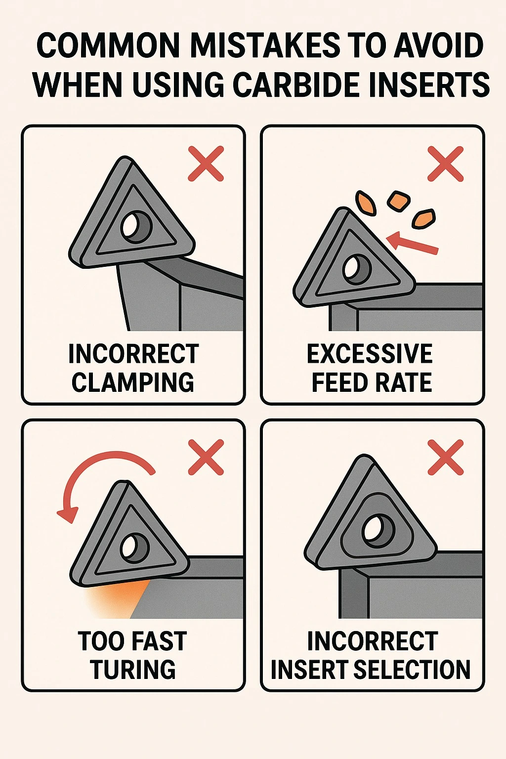
Top mistakes (and how to fix them)
Below are the most common mistakes we see on shop floors — each with a plain-English explanation, the why, and an action you can take right away.
Mistake 1 — Choosing the wrong grade or coating for the material
Why it happens: Buyers pick a “general” grade or emulate a competitor’s setup without checking material group (ISO P/M/K/N/S/H).
Why it matters: Wrong grade accelerates flank wear, built-up edge, or catastrophic chipping. Different coatings (PVD vs. CVD) and carbide substrates behave differently at temperature and under deformation.
Fix: Match the grade to the workpiece family (e.g., ISO P = steels, M = stainless, K = cast iron, N = non-ferrous). If you need high temperature resistance (e.g., titanium/HRSA), choose specialized grades. Use vendor grade guides (Sandvik, Kennametal, Iscar) for recommended combinations.
Mistake 2 — Misreading ISO insert nomenclature (ordering wrong geometry)
Why it happens: Confusing the positions (e.g., swapping nose radius digits or misunderstanding the clearance letter).
Why it matters: You can receive an insert with the wrong relief, radius, or hole, making it unusable or unsafe.
Fix: Keep an ISO 1832 reference (or vendor designation key) at the purchasing desk; cross-check dimensions with drawings before ordering. Manufacturer PDFs (Walter, Sandvik) show the designation keys clearly.
Mistake 3 — Poor clamping, seating, or torque on the insert
Why it happens: Under tightened clamps or debris between insert and seat; or over-torquing damaging the insert or clamp.
Why it matters: Insert movement causes edge chipping, chatter, or concentricity errors.
Fix: Clean seat and insert interface, use the correct screw/clamp and torque value from the toolholder maker, and inspect seating surfaces for burrs. Replace worn clamp plates promptly. (Toolholder manuals list torque values.)
Mistake 4 — Running wrong cutting speed / feed for the grade & geometry
Why it happens: Copying settings from a different material or insert without adjustment.
Why it matters: Too high speeds cause thermal failure; too low speeds with the wrong feed cause rubbing and built-up edge.
Fix: Use manufacturer-recommended ranges as starting points, then adjust based on chip shape, tool wear, and surface finish. Sandvik and Kennametal provide grade-based starting tables.
Mistake 5 — Using a turning insert in a milling application (or vice versa)
Why it happens: Assuming a geometry works in both operations.
Why it matters: Milling inserts often have positive geometries and different clamping requirements; negative turning inserts are designed for heavy radial loads. Using them interchangeably leads to premature failure or poor finish.
Fix: Use the insert family intended for the operation. Check whether the insert is family-rated for milling or turning.
Mistake 6 — Not checking insert tolerance/accuracy (positional fit)
Why it happens: Overlooking the tolerance letter in the ISO code.
Why it matters: Low-tolerance inserts in high-precision holders cause runout and poor geometry.
Fix: For precision components, specify higher tolerance inserts (e.g., H class). Confirm fit with toolholder specs.
Mistake 7 — Poor coolant/lubrication choices
Why it happens: Running dry when the grade/coating expects coolant, or over-cooling an insert that benefits from heat-resistant performance.
Why it matters: Can degrade coating performance (PVD vs CVD), cause thermal cracking, or promote built-up edge.
Fix: Follow manufacturer recommendations — some PVD grades prefer dry/high-pressure air, others need MQL or flood. Sandvik and industry guides explain coating compatibility.
Mistake 8 — Reusing inserts beyond safe wear limits
Why it happens: Trying to stretch tool life to save cost.
Why it matters: Increased scrap, inconsistent parts, machine downtime.
Fix: Monitor flank and crater wear; index or replace inserts before wear exceeds manufacturer limits. Use insert identifier tools or vendor apps to find equivalents and replacements.
Mistake 9 — Storage & handling errors
Why it happens: Inserts stored loosely, exposed to dirt or moisture.
Why it matters: Corrosion of coating edges, chipping from tumble damage, or mixing different geometries.
Fix: Store inserts in original packs or dedicated bins, label bins with ISO codes, and handle by the sides (not by cutting edge).
Coatings: PVD vs CVD (short, practical guide)
- CVD (Chemical Vapor Deposition): deposited at high temperature (700–1,050 °C), often results in thicker oxide layers (e.g., Al₂O₃) with excellent wear resistance. Great for long life where the substrate tolerates heat.
- PVD (Physical Vapor Deposition): deposited at much lower temperatures (≤ 500 °C), leaves thinner, harder films (e.g., TiAlN) and preserves substrate toughness. Better for substrates or geometries that cannot be exposed to high coating temperatures.
Practical tip: Don’t swap PVD/CVD blindly — use manufacturer grade tables for the material you cut.
Practical use cases by industry
- Automotive: High volumes, mixed steels — favor robust turning inserts with chip control and economical grades. Many shops use CNMG and DNMG for general turning.
- Aerospace: Titanium and nickel-based alloys (HRSA) need specialized grades (often ceramic or optimized CVD/PVD carbide) and conservative parameters.
- Die & Mold: Tight surface finish — choose wiper geometries and ground edges (G in the ISO code) for finish passes.
- General machining / job shops: Versatile medium grades and good chipbreakers are typical; keep an inventory of common ISO geometries for fast changeovers
Brand comparison (neutral, factual)
Major brands (Sandvik Coromant, Kennametal, Iscar, Walter, Seco) provide overlapping but differentiated portfolios:
- Sandvik Coromant — extensive grade guides and tooling systems; strong online knowledge base for grade selection. Kennametal — broad product catalog with many CNMG/turning offerings and clear product pages listing application notes.
- Iscar — deep work on chip control and specialized chipbreaker geometries; strong technical literature on chipforming. I
Neutral advice: Use vendor data sheets to find the grade and chipbreaker best suited to your application; test on a single part before full production.
A step-by-step checklist to avoid mistakes (quick)
-
Identify material family (ISO P/M/K/N/S/H).
-
Read the ISO code correctly (use ISO 1832 key).
-
Choose grade & coating for the material and operation (consult vendor grade tables).
-
Match chipbreaker to feed/depth and material
-
Clean seating surfaces and torque clamps per toolholder spec.
-
Start at vendor recommended speeds/feeds and adjust by observing chips & wear.
-
Inspect inserts regularly; index or replace before reaching critical wear.
Conclusion & CTA
Small mistakes with carbide inserts create outsized problems. By following ISO 1832 nomenclature, matching grade/coating to material, selecting proper chipbreakers, and using correct clamping and speeds, you protect part quality and reduce cost. Ready to compare trusted brands and real-world part numbers? Explore CNC Tools Depot’s marketplace for Sandvik, Kennametal, Iscar and more — curated by experts to help you pick the correct carbide inserts fast.
Shop smarter — reduce scrap, improve uptime. Visit CNC Tools Depot to search by ISO code, material, or application
Frequently Asked Questions
CNMG breaks down via ISO 1832: C = 80° diamond shape, N = 0° clearance, M = medium tolerance, G often indicates ground cutting edge/type. The following numbers indicate size, thickness, and nose radius. Always verify against the vendor designation key.
Stainless (ISO M) typically needs grades with higher toughness and special coatings to avoid built-up edge (BUE). Look for inserts and chipbreakers the vendor lists for stainless applications — Sandvik and Kennametal provide grade recommendations for ISO M materials. Test on your part to confirm. Sandvik Coromantkennametal.com
Use the ISO 1832 positions: shape, clearance, tolerance, type, size (IC), thickness, nose radius. Vendor designation keys (Walter, Sandvik) give a direct mapping and charts.
CVD is applied at higher temperatures and yields thicker oxide layers with great wear resistance; PVD is applied at lower temperatures, giving thinner, hard films that preserve substrate toughness. The right choice depends on material and cutting conditions
CNC Tools Depot aggregates trusted brands and product listings, supports ISO code searches, and provides clear cross-references so you can compare Sandvik, Kennametal, Iscar, and others side-by-side. Use our catalogue to search by ISO code, material group, or chipbreaker style.
Replace/index before flank wear (or crater wear) exceeds vendor limits, or before surface finish and tolerance drift outside part spec. Monitor chips and measure wear — vendor app/tools can help identify equivalents

India's Largest Marketplace for Carbide Inserts & Cutting Tools.
© 2026. All Rights Reserved
Disclaimer: All Brand Logos belong to their respective owners, CNC Tools Depot is sharing publicly available information