Login / Register

Verify OTP

Update Profile

Choosing Carbide Inserts for CNC Lathe Operations
Learn how to choose the right carbide inserts for CNC lathe operations. Understand ISO codes, geometry, coatings, and grades with expert guidance from CNC Tools Depot.
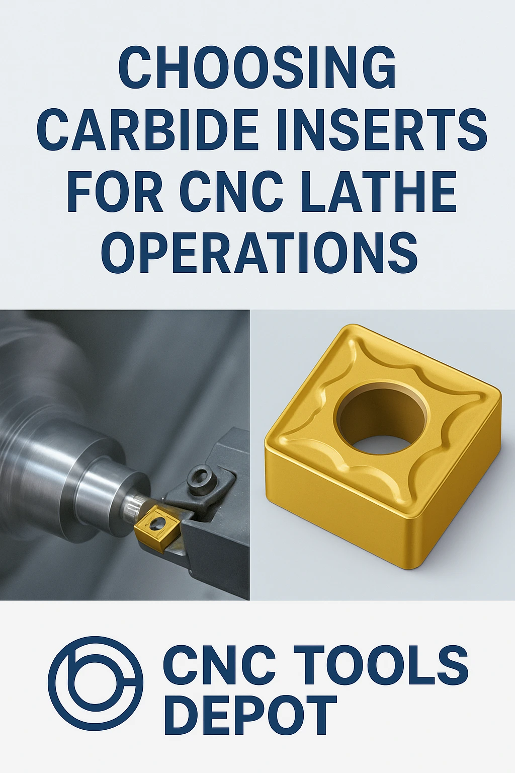
Selecting the correct carbide inserts for CNC lathe operations is essential for achieving precision, surface finish, and cost efficiency. This expert guide from CNC Tools Depot — the world’s largest marketplace for carbide inserts — explains how to decode ISO 1832 insert nomenclature, select the right geometry, clearance angles, chipbreakers, and coatings, and match insert grades to different materials like steel, stainless steel, and superalloys.
With practical examples, comparisons across leading brands (Sandvik, Kennametal, Iscar, Mitsubishi), and step-by-step instructions, the article bridges technical detail with easy-to-understand explanations. Whether you’re an engineer, machinist, or buyer, you’ll gain the knowledge to make confident tooling decisions and improve CNC lathe performance.
Why the right insert matters
CNC lathe operations are the backbone of high-volume parts production and precision components. The carbide insert you choose governs dimensional accuracy, surface finish, cycle time and tool-cost-per-part. Pick the wrong geometry, grade or chipbreaker and you’ll see chatter, poor surface finish, shortened tool life and unpredictable scrap — pick the right one and you get repeatable precision and lower total cost. Manufacturer selection guides and ISO designation standards make that choice repeatable across suppliers.
Quick primer: what the ISO code tells you (ISO 1832)
Indexable inserts are labeled with ISO codes so you can order like-for-like geometry from any brand. Example: CNMG120408 — decode it like this:
- C — insert shape: 80° rhombic (diamond).
- N — clearance/relief angle: 0° (neutral/negative relief).
- M — tolerance/edge-prep/manufacturing modifier (commonly used to indicate a medium tolerance/series — check ISO & supplier key).
- G — chipbreaker/clamping/ground indicator (varies by supplier).
- 12 — inscribed circle (IC) size — ~12.7 mm in metric form.
- 04 — thickness (≈ 4.76 mm).
- 08 — nose radius 0.8 mm.
ISO 1832 defines the allowed code positions and nominal dimensions — use the ISO text and manufacturer designation keys (Walter, Sandvik, Kennametal) to convert codes to exact part dimensions and allowed variations.
Choose an insert
Follow this concise workflow to make a repeatable choice.
1) Define the machining objective
Are you roughing (remove stock fast) or finishing (tight tolerance/surface finish)? Objective drives geometry, nose radius and grade.
2) Match insert shape & nose radius to the task
- Large nose radius (≥0.8 mm) for stable finishes and long tool life in roughing.
- Small radius (≤0.4 mm) for fine detail and thin-walled parts.
- Shape choice (C, D, T, W, etc.) determines approach angle and available cutting-edge length.
3) Choose the correct clearance (relief) & lead angles
Relief angle affects contact and tool strength — negative/neutral (N) for rugged cuts, positive rake for low cutting force finishing.
4) Select grade & coating to suit the material
Use manufacturer grade charts: tougher substrates for interrupted cuts, PVD or CVD coatings to reduce adhesion and crater wear depending on workpiece material. Start with supplier-recommended speeds and feeds and validate with a short trial.
5) Pick a chipbreaker matched to feed & depth of cut
Chipbreaker geometry controls chip shape, affects edge temperature and surface finish — suppliers publish maps linking feed/ap to chipbreaker types.
6) Validate on the machine and iterate
Run a short trial, measure flank wear and dimensional drift, then incrementally optimize speed and feed.
Technical deep dive
Geometry, chipbreakers & edge prep — plain-language explanations
- Geometry (shape & nose radius): imagine the cutter as a shoe sole — a bigger radius spreads load and gives smoother contact, a sharper corner gives detail but concentrates forces. Larger contact area can improve finish but increases cutting forces.
- Chipbreaker: like a papercutter that slices chips into safe pieces — the right chipbreaker prevents long stringy chips, reduces tool temperature and protects the edge. Manufacturers design chipbreakers for specific feed and depth ranges.
- Edge prep: honing, chamfering or a defined edge strengthens the cutting edge and reduces chipping during interrupted cuts. Use ground (G) or prepared edges per ISO code and supplier specs.
Grades and coatings — choosing for material groups
- Steel (including alloy steels): many PVD TiAlN or multi-layer CVD grades work well; choose finer-grain carbides for finishing and tougher substrates for interrupted cuts.
- Stainless & nickel alloys (superalloys): select grades that resist adhesion and crater wear (specialized PVD or high-temperature CVD stacks). Lower cutting speeds, higher feeds and good coolant strategies are typical.
- Cast iron & non-ferrous: different wear modes — match coatings and chipbreakers accordingly. Manufacturer application guides provide material-by-material recommendations.
Brand-neutral comparison
Sandvik Coromant: robust knowledge base for turning and chip control; great starting point for selecting geometry and coolant strategy.
Kennametal: extensive grade-selection systems and conversion charts for switching grades or suppliers. Their catalogs provide conversion and grade comparison tools.
Walter / Seco / Iscar / Mitsubishi: all publish ISO-coded product pages that let you match CNMG/CNGN family inserts across vendors. Use ISO codes and the supplier’s designation keys to verify exact dimensions and chipbreaker types.
How to compare: order by ISO code (geometry standardized by ISO 1832) and then compare grade/coating/ chipbreaker descriptions and recommended application ranges from each supplier.
Practical examples
- High-volume automotive shaft turning: CNMG/CNGN with robust negative geometry for roughing, PVD-coated fine-grain grades for finishing to maintain tight diameters and surface finish; short tool overhangs and steady rest for long shafts.
- Aerospace small-batch components: use ground inserts with precise nose radii and specialty grades that keep dimensional stability under thermal and cutting loads. Validate with sample runs.
Frequently Asked Questions
It’s an ISO 1832 designation: C = 80° rhombic shape, N = 0° clearance, M = tolerance/manufacture modifier, G = chipbreaker/ground indicator; 12 = IC size (~12.7 mm), 04 = thickness (~4.76 mm), 08 = 0.8 mm nose radius. Verify exact dimensions in ISO 1832 and supplier keys.
Facing often uses larger nose radii and shapes with broad corner support (W/T shapes); external turning depends on required approach angle — CNMG is a common general-purpose negative shape for robust turning. Check the operation and tooling handbook for the best fit.
Use PVD when you need a sharp edge and reduced adhesion (finishing, many alloy steels), and CVD when thermal and abrasive resistance is priority (some roughing/high-temp operations). Always consult supplier application guidance.
Yes—ISO 1832 standardizes geometry codes so you can match shapes and sizes across brands. Be aware that grades, coatings and chipbreaker designs differ, so validate performance by trial.
Consult the manufacturer’s chipbreaker map — they publish feed and depth-of-cut ranges for each chipbreaker type. Start within the recommended range and adjust for your machine rigidity and coolant strategy.
Manufacturer catalogs and technical guides from Sandvik, Kennametal, Walter and others include recommended speeds/feeds per grade and material group — use those as your baseline and run validation tests.

India's Largest Marketplace for Carbide Inserts & Cutting Tools.
© 2026. All Rights Reserved
Disclaimer: All Brand Logos belong to their respective owners, CNC Tools Depot is sharing publicly available information