Login / Register

Verify OTP

Update Profile

Carbide Inserts for Heavy-Duty Machining Applications
Learn how to choose the best carbide inserts for heavy-duty machining. Covers ISO codes, insert geometry, coatings, chipbreakers, and practical shop tips.
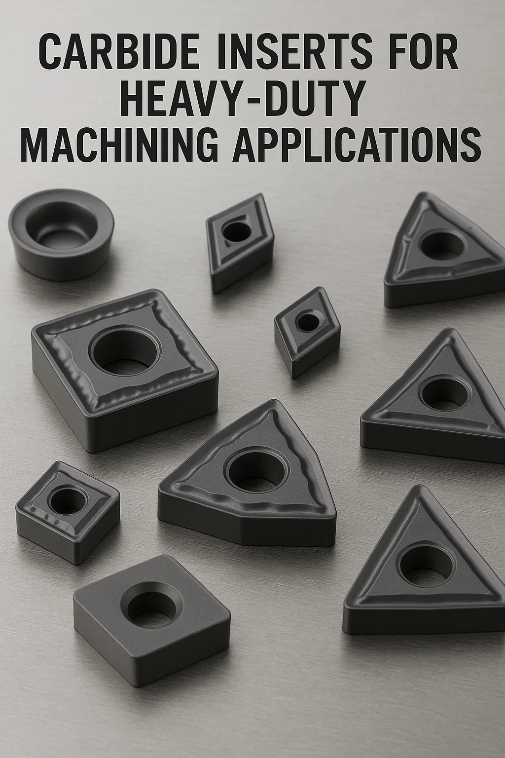
Heavy-duty machining requires carbide inserts built to withstand extreme cutting forces, heat, and interrupted cuts. This in-depth guide from CNC Tools Depot explains how to select the right ISO 1832-coded carbide inserts for turning, milling, grooving, and boring applications.
We break down insert geometry (shape, clearance, nose radius), substrate grades, and coatings (CVD, PVD, ceramic, CBN) in plain language, comparing approaches from brands like Sandvik, Kennametal, and Iscar. Practical sections highlight chipbreaker design, edge preparation, toolholding strategies, and real-world industry use cases in automotive, aerospace, and general machining.
Whether you’re a machinist, engineer, or buyer, this blog provides actionable steps and expert insights to maximize tool life, productivity, and cost efficiency in heavy-duty CNC cutting operations.
Overview
Why heavy-duty machining deserves its own playbook
Heavy-duty machining (HDM) — large depths of cut, high material removal rates, interrupted cuts and large components — places extreme mechanical, thermal and dynamic loads on the cutting edge. The right carbide insert turns expensive problems (broken tools, poor part geometry, costly downtime) into predictable, high-throughput production. This guide explains how to choose ISO-specified carbide inserts, coatings, and toolholding strategies that maximize productivity and tool life in heavy-duty lathe and milling operations.
What “heavy-duty machining” means
Heavy-duty machining typically involves combinations of:
- High depth of cut (ap) — e.g., several millimeters up to tens of mm in roughing.
- High feed per tooth or per revolution (f) to remove large volumes.
- Interrupted or roughing cuts (castings, billets, part features).
- Large cross sections and heavy overhangs requiring high cutting forces.
These conditions drive the need for very robust insert geometry, high-toughness substrates, and coatings that withstand heat, abrasion and edge chipping.
ISO 1832 primer — reading insert codes
ISO 1832 standardizes insert designation. A sample code: CNMG120408 — break it down:
- C — shape = 80° rhombic (diamond).
- N — clearance/relief angle = 0° (neutral/negative).
- M — tolerance/manufacture series symbol (manufacturer key).
- G — chipbreaker/ground/clamping modifier (vendor-specific).
- 12 — inscribed circle (IC) size ≈ 12.7 mm.
- 04 — thickness (≈ 4.76 mm).
- 08 — corner radius = 0.8 mm.
Use ISO 1832 tables plus supplier datasheets to verify exact dimensions and permitted tolerances before ordering replacements for heavy-duty tooling. Knowing the code ensures you get the same geometry across brands.
Insert geometry
Shape & approach angle
- Negative-rake shapes (e.g., CNMG, SNMG, DNMG in negative grades) give edge strength and stability for heavy interrupted cuts. Their larger wedge section resists plastic deformation and chipping.
- Positive-rake shapes reduce cutting force — useful for finishing passes but generally not for the deepest roughing cuts in HDM.
Clearance / relief angle
- Neutral or small clearance (0° or few degrees) increases support behind the cutting edge for heavy loads; it reduces edge deflection and fracture risk.
Nose radius & corner strength
- Large nose radii spread load and increase durability, but increase cutting forces and require more spindle power. For roughing, choose a robust radius (e.g., ≥1.2 mm and larger for very heavy cuts); smaller radii are reserved for finishing/detailing.
Wedge thickness & chip pocket
- Thicker inserts provide more core strength. For heavy milling, consider indexable milling cutters with thicker insert pockets and reinforced clamping.
Technical deep dive
Carbide substrate & grain
- Coarse or mixed grain cobalt-bonded carbides deliver better fracture toughness (resist chipping in interruptions).
- Fine-grain carbides give higher wear resistance but lower toughness — better for finishing or stable conditions.
Coatings: practical guidance
- CVD (thicker ceramic layers like Al₂O₃/TiCN): excellent thermal/abrasive resistance. Many heavy-duty grades use CVD stacks to protect carbide from high temperatures and abrasion.
- PVD (TiAlN, AlTiN, etc.): thinner, adherent films that can increase hot hardness; useful where sharp edges and less aggressive roughing are used.
- Multi-layered coatings: modern HDM grades frequently use multi-layer or hybrid coatings to combine adhesion resistance and thermal barrier effects.
Ceramic & CBN
- Ceramic inserts (SiAlON, alumina-based): excel at high cutting speeds and thermal stability for continuous heavy cuts but are brittle — avoid interrupted cuts.
- CBN: primarily for hardened steels and some finish applications; rarely first choice for raw heavy bulk removal in non-hardened steels.
Rule of thumb: For unpredictable, interrupted heavy cuts choose tough carbide substrates with robust CVD or hybrid coatings. For extremely stable, high-speed continuous roughing, evaluate ceramic inserts.
Chipbreakers, edge prep & chip control
- Open or heavy-duty chipbreakers are designed to manage large chip sections and avoid chip packing in the cutter pocket.
- Edge prep (hone/chamfer): a small honed edge or chamfer (e.g., K or M style edge prep) increases edge strength and reduces micro-chipping under shock.
- Wiper styles are not typical for first-pass roughing but useful for semi-finishing where higher feeds and good surface finish are desired.
Always match the chipbreaker to the feed range; manufacturer chipbreaker maps show the intended feed/ap windows.
Toolholding, clamping and process stability
Tool geometry without stable holding fails. For heavy loads:
- Minimize insert overhang and use short, stiff toolholders.
- Use reinforced clamping (positive clamps, multiple screws, wedge systems). Secure clamping prevents insert slip and edge fracture during heavy impacts.
- Check spindle power & torque to ensure the machine can deliver required cutting power without stalling.
- Consider damped adaptors or heavy-duty boring bars for long-reach applications.
- Ensure accurate seat and pocket dimensions — incorrect seat tolerance magnifies runout and stress.
Choosing inserts
Heavy turning (roughing)
- Shape: robust negative inserts (CNMG, TNMG, SNMG negative variants).
- Grade: tough carbide, multi-layer CVD or hybrid coatings.
- Edge prep: honed/chamfered.
- Coolant: high flow or MQL per grade recommendations.
Heavy milling (face milling, shoulder milling)
- Shape: square/round inserts with thick cross-sections and reinforced clamping.
- Chip pocket: designed for large chip volume and evacuation.
- Indexable milling cutters with many inserts and staggered indexing help distribute load.
Grooving & parting
- Use purpose-built grooving inserts with reinforced necks and high toughness grades; avoid brittle ceramic here.
Boring & OD/ID heavy cuts
- Heavy boring bars need thick, positive/negative tipped inserts and support to avoid chatter.
Frequently Asked Questions
Only when cuts are stable and uninterrupted — ceramics excel at high speeds in continuous cuts but are brittle and risky in interrupted heavy machining. For mixed or interrupted heavy work, use tough carbide grades.
Critical. Proper clamping prevents insert slip, reduces stress peaks, and lowers the chance of catastrophic edge fracture. Use reinforced clamps, correct torque and confirm pocket fit.
For heavy, abrasive or high-thermal loads, CVD or hybrid coatings often provide better thermal & abrasion resistance. PVD may be suitable where sharper edges and less abrasive work are present.
Not optimally. Roughing needs edge strength and larger radii; finishing benefits from finer grain and sharper edges. Many shops use different inserts for rough and finish passes to optimize both cycle time and quality.

India's Largest Marketplace for Carbide Inserts & Cutting Tools.
© 2026. All Rights Reserved
Disclaimer: All Brand Logos belong to their respective owners, CNC Tools Depot is sharing publicly available information