Login / Register

Verify OTP

Update Profile

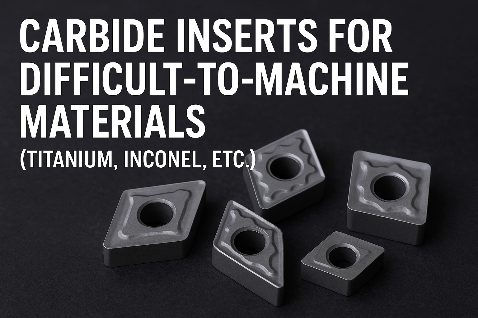
Carbide Inserts for Difficult-to-Machine Materials (Titanium, Inconel, etc.)
Learn how to select the right carbide inserts for machining titanium, Inconel, and other difficult alloys. Covers ISO 1832 codes, coatings, chipbreakers, and best practices with insights from top brands at CNC Tools Depot.
Machining titanium, Inconel, and other high-performance alloys presents unique challenges such as rapid tool wear, heat concentration, and work-hardening. This in-depth guide from CNC Tools Depot — the world’s largest marketplace for carbide inserts — explains how to choose the right carbide inserts, turning inserts, and milling inserts for difficult-to-machine materials.
You’ll learn how to read ISO 1832 insert nomenclature (codes like CNMG 120408), understand the impact of geometry, chipbreaker design, and coatings (CVD vs. PVD), and select insert grades optimized for aerospace, medical, oil & gas, and power-generation applications. Backed by verified references from Sandvik, Kennametal, Iscar, and other leading brands, this article bridges technical detail with plain-language explanations — making it easy for engineers, machinists, and buyers to make confident decisions.
Whether you’re cutting titanium implants, Inconel turbine disks, or other superalloy components, this guide provides step-by-step insert selection strategies, practical machining tips, and brand-neutral comparisons. Explore CNC Tools Depot to compare and source the best carbide inserts across all major manufacturers — all in one trusted marketplace.
Introduction
Why this matters
Titanium and nickel-base superalloys (Inconel, Rene, Haynes families) are the backbone of aerospace, power-generation, oil & gas and high-performance motorsport components. They give incredible strength-to-weight and temperature resistance — but that also makes them hard on tooling. Choosing the right carbide inserts, geometry, coating and grade is the single biggest lever you have to get predictable tool life, part quality and cycle time when machining these alloys. Below you’ll find an approachable, technically accurate playbook (ISO nomenclature included) for selecting and applying inserts in these demanding materials.
What makes Titanium & Inconel difficult to machine?
Short version: they concentrate heat at the cutting edge, work-harden rapidly, and often “stick” to tool edges.
- Low thermal conductivity (titanium): heat stays in the chip and tool edge, increasing adhesive wear and promoting built-up edge.
- High strength at temperature (Inconel / HRSA): the alloy doesn’t shear easily and tends to gall/crater tool edges; machining creates high cutting forces and rapid flank wear.
- Work-hardening and chemical affinity: some nickel alloys work-harden ahead of the tool; titanium chemically reacts with tool surfaces at high temperatures, accelerating notch and crater wear.
Quick primer: ISO 1832 insert nomenclature (how to read CNMG 120408)
ISO 1832 defines the standard code for indexable inserts. The full code can have 12–13 symbols, but positions 1–7 are the most commonly used for turning inserts. A typical code: C N M G 12 04 08 (often written in compact form as CNMG120408). The positions mean:
-
Shape — e.g., C = 80° rhombic (diamond).
-
Relief / Clearance angle — N = 0° (neutral/negative), B = 5°, C = 7°, etc.
-
Tolerance / manufacturing type — M or G (M = molded/standard tolerance, G = ground/tighter tolerance in some positions).
-
Clamping / chipbreaker / cross-section modifier — letters here often indicate whether the insert is ground, has a chipbreaker geometry on face/back, special hole/countersink, etc. (in CNMG the “G” typically indicates a standard clamping/chipbreaker configuration).
-
Insert size / inscribed circle (IC) — e.g., 12 = 12.7 mm IC in metric listings.
-
Thickness (s) — e.g., 04 = ~4.76 mm for common CNMG metric sizes.
-
Corner radius — 08 = 0.8 mm nose radius (08 → 0.8 mm).
Practical translation (CNMG120408):
C = 80° diamond, N = 0° clearance (negative/neutral rake application), M = common tolerance type, G = standard clamping/chipbreaker style; IC ≈ 12.7 mm, thickness ≈ 4.76 mm, nose radius ≈ 0.8 mm. Use the ISO charts for exact tolerances and dimensions.
How geometry, grade & coating interact for titanium and Inconel
Think of the cutting situation as a three-legged stool: (1) geometry, (2) substrate/grade, (3) coating. If any leg fails, tool life and process reliability suffer.
1) Geometry & edge prep (what to choose)
- Positive vs negative geometry: For titanium and interrupted cuts, a positive geometry with larger rake reduces cutting forces; for heavy roughing and high depth of cut on HRSAs you may favor robust negative geometries for edge strength.
- Relief (clearance) angle: Neutral/0° (N) or small positive relief is common—0° (negative) inserts provide edge strength for interrupted or heavy cuts; positive relief reduces cutting force and heat for finishing.
- Nose radius: Larger nose radii (0.8 mm and above) improve tool life in roughing; small radii (≤0.4 mm) for finishing and thin walls.
- Chipbreaker: A purpose-built chipbreaker is essential; the right chipbreaker breaks long, stringy chips (titanium) into controlled segments and reduces edge temperature. Use chipbreakers designed for the intended feed/ap ranges.
2) Grade & substrate
- For titanium: choose tough carbide substrates with good fracture resistance (to resist chipping) and grades optimized for adhesion resistance. Some manufacturers offer special "titanium" grades.
- For Inconel / HRSA: pick grades that resist abrasive flank/crater wear and maintain hardness at elevated temperatures (some PVD grades or specialty substrates). Ceramic inserts are used for high-speed roughing in some cases, but carbide grades are widely used across finishing and intermediate stages.
3) Coating: PVD vs CVD (short guidance)
- CVD coatings (e.g., Al₂O₃ + TiCN) often provide thermal barrier behavior and excellent abrasion/crater resistance — good for some HRSA and high-temperature roughing scenarios.
- PVD coatings (e.g., AlTiN, TiAlN) tend to be thinner, produce a sharper edge, and are commonly used in finishing and last-stage machining; they can reduce adhesion and improve life in many titanium and nickel alloy operations. Modern PVD grades are tailored for HRSA and titanium as well.
Rule of thumb: use a tough substrate + coating that resists adhesion and crater wear; choose CVD for abrasion/high heat demands and PVD when a sharp, tough edge and lower adhesion are priorities — but always validate on the specific alloy and operation.
Step-by-step selection checklist
- Identify operation & constraints (roughing vs finishing, depth of cut, rigidity, coolant availability).
- Pick geometry: negative/robust for heavy/interrupted cuts; positive for finishes and thin walls. Choose nose radius per finish requirement.
- Select chipbreaker matched to feed and depth of cut — manufacturers provide chipbreaker charts (use them).
- Choose grade & coating: prioritize toughness for titanium and wear/thermal resistance for Inconel. Start conservative and optimize speeds.
- Validate with a short test: measure tool wear, surface finish, and check for chatter. Increase speed if wear remains acceptable. (Manufacturer grade charts are your baseline.)
Practical Examples
- Aerospace (turbine disks, shafts): often machined from Inconel 718 or RR-1000; require stable holders, small step-downs, PVD-tough carbide grades or ceramics for high-speed roughing, and strict tool change windows.
- Medical implants (titanium): finishing and surface integrity matter; use sharp edges, PVD TiAlN-type coatings and small feeds for a high surface finish.
- Oil & gas / power generation: Inconel components need robust insert geometries and frequent tool life monitoring; manufacturers provide HRSA-specific grades.
Brand notes
- Sandvik Coromant publishes dedicated grade chains and application guides for titanium and HRSA and tools that focus on damping and coolant delivery for HRSAs.
- Kennametal offers chipbreaker geometry families and practical tips (rigidity, coolant placement) for titanium milling/turning.
- IScar, Mitsubishi, Tungaloy, Widia and others supply CNMG/CNGN families and HRSA/titanium-targeted grades — cross-reference their data sheets to match ISO codes and grade charts.
Frequently Asked Questions
CNMG is an ISO shape/geometry code: C = 80° rhombic shape, N = 0° clearance, M = tolerance/manufacture type, G = chipbreaker/clamping style. The following numbers (e.g., 120408) give size, thickness and nose radius. See ISO 1832 for exact mappings.
There’s no one “best” insert — choose by family: for stainless use grades balancing toughness/wear (often PVD), for titanium prioritize tough substrates + adhesion-resistant coatings and chipbreakers, and for Inconel use grades with high wear/thermal resistance (sometimes PVD or specially engineered CVD stacks). Always cross-check manufacturer grade charts.
Break the code into symbol groups: shape, clearance, tolerance, clamping/chipbreaker, IC size, thickness, nose radius. (Full ISO 1832 charts list all permitted letters and numbers.) Use supplier datasheets for the exact metric/inch conversion.
CVD typically gives a thicker, harder Al₂O₃/TiCN layer that is thermally robust (good for abrasion/high-heat roughing). PVD is thinner and can give a sharper, tougher edge (good for finishing, reduced adhesion). The best choice depends on material and operation.
Very important. Long, stringy chips (titanium) or hard chips (Inconel) cause tool damage and operator hazards. Use chipbreakers engineered for the intended feed/ap — manufacturers provide charts that match feed and ap ranges to chipbreaker types.

India's Largest Marketplace for Carbide Inserts & Cutting Tools.
© 2026. All Rights Reserved
Disclaimer: All Brand Logos belong to their respective owners, CNC Tools Depot is sharing publicly available information