Login / Register

Verify OTP

Update Profile

Carbide Inserts FAQs: Everything Machinists Need to Know
Get clear answers to the most common questions about carbide inserts. Learn how to read ISO 1832 insert codes, choose the right chipbreaker and coating, and select inserts for turning and milling applications. CNC Tools Depot stocks all leading brands—Sandvik, Kennametal, Iscar, Korloy, Widia, Kyocera, Mitsubishi, and more.
Carbide inserts are the backbone of modern CNC machining, but choosing the right insert can be confusing. This comprehensive FAQ explains everything machinists need to know—ISO insert nomenclature, clearance angles, chipbreaker designs, coatings (CVD vs. PVD), and ISO 513 material groups. You’ll learn how to decode codes like CNMG120408, understand when to use positive vs. negative rake inserts, and match the right grade to your workpiece material, whether it’s steel, stainless steel, cast iron, aluminum, or heat-resistant alloys. We also compare major brands—Sandvik, Kennametal, Iscar, Korloy, Kyocera, Mitsubishi, Taegutec, and Widia—so you can see what’s standardized and what’s proprietary. Whether you’re machining automotive parts, aerospace alloys, die & mold components, or general job-shop work, this guide simplifies insert selection for better performance, tool life, and cost efficiency. Explore CNC Tools Depot’s unmatched selection of turning inserts, milling inserts, and grades, all backed by expert technical guidance.
Introduction
Why this matters in CNC machining
Carbide inserts are the workhorses of CNC cutting tools. Get the insert wrong and you fight chatter, built-up edge, poor surface finish, tool breakage, and wasted cycle time. Get it right and you unlock predictable turning and milling performance, longer tool life, and lower cost per part. This FAQ distills the essentials—ISO insert nomenclature, chipbreakers, coatings, material groups, and brand nuances—so both engineers and shop-floor machinists can make confident choices.
The quick idea: ISO codes are your insert’s “license plate”
Every indexable insert carries a standardized code (ISO 1832). Think of it like a license plate: each character tells you something—shape, clearance angle, tolerance class, clamping/chipbreaker style, size, thickness, nose radius, and optionally geometry and material group. Understanding these symbols lets you cross-shop brands (Sandvik, Kennametal, Iscar, Korloy, Kyocera, Mitsubishi, Taegutec, Widia, etc.) with confidence.
How to read ISO 1832 (step-by-step)
Let’s decode a common turning insert:
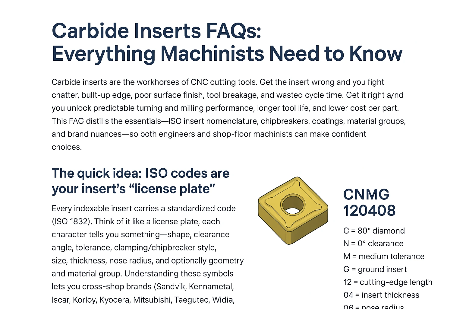
Example: CNMG 12 04 08 (often seen as CNMG 120408)
-
C — Shape: 80° rhombic (commonly called an 80° diamond).
-
N — Clearance angle: 0° (negative style; strong edges, double-sided).
-
M — Tolerance class: “M” class tolerances (a widely used class for molded inserts per ISO tables).
-
G — Fixing/chipbreaker type: insert with hole and chip grooves on both rake faces (does not mean “ground” here).
-
12 — Cutting-edge length (l) code (metric series; actual mm depends on shape per ISO table).
-
04 — Insert thickness code (e.g., code 04 corresponds to s ≈ 4.76 mm in ISO tables).
-
08 — Nose radius code (r = 0.8 mm).
-
Optional geometry/material code (e.g., -PM for a medium-duty steel chipbreaker; P for ISO steel material group).
Tip: Numbers in positions 5–7 are codes, not raw millimeters in every case. ISO provides the mapping tables (e.g., 04 → 4.76 mm thickness; 08 → 0.8 mm nose radius). Always check the table or the manufacturer’s dimension page when you need exact mm.
Jargon, translated
- Clearance angle (relief): the angle between the clearance face and the work. 0° (N) “negative” inserts are stronger and typically double-sided; 11° (P) and other positive clearances cut freer, great for low-power machines, small diameters, or gummy materials.
- Tolerance class: ISO letters (e.g., M, G, H) specify permissible deviations of key dimensions (IC/edge length, thickness). Pick tighter tolerance where indexing accuracy and surface finish matter (finishing), and standard classes for roughing.
- Fixing/chipbreaker letter (position 4): e.g., G means with hole + chipbreakers on both faces—it describes clamping and chip-groove presence/side, not edge sharpness.
Chipbreaker geometry (what “-PM, -MM, -SM, -RM” really do)
Chipbreakers are sculpted grooves and lands that control chip curl, cutting forces, and heat. Makers label them by duty window (finishing/medium/roughing) and often by material family (P/M/K/N/S/H).
- Finishing (F): freer cutting, stable small chips at low depth of cut and feed.
- Medium (M): broad window; your everyday geometry for general turning.
- Roughing (R/H): stronger edges for higher feeds and depth, with robust chip control.
Manufacturers publish “feed–ap windows” for each breaker; match your setup to the window for predictable chips and tool life.
Brand-to-brand: what changes, what doesn’t
- What doesn’t change: The ISO 1832 code—so a CNMG 120408 from Sandvik, Kennametal, or Iscar shares shape/size fundamentals.
- What does change: Grade metallurgy, coatings, and chipbreaker design. For instance, you’ll see different P/M/K ranges and breaker names (e.g., Sandvik -PM, Kennametal -LF/-MF, Iscar -F3P). Always compare the published application charts for your material and duty.
CVD vs PVD
- CVD (Chemical Vapor Deposition): typically thicker, very wear-resistant coatings (e.g., TiCN/Al₂O₃/TiN stacks). They shine in continuous turning at higher speeds in steels/cast irons where hot-hardness and crater/abrasive wear resistance dominate.
- PVD (Physical Vapor Deposition): thinner, tougher, and applied at lower temperature—great for sharp edges, interrupted cuts, milling, threading, and finishing at low–medium speeds, or when adhesion risk (BUE) and edge chipping are concerns.
Turning vs. milling inserts
- Turning inserts (CNMG, VNMG, SNMG…): edges optimized for continuous/semi-interrupted cuts; negative styles offer two usable sides/4–8 edges.
- Milling inserts (APKT, SEKT, RCMX…): edges tailored for interrupted cutting, positive rake to reduce force and vibration, and seat geometries built for cutter bodies. (You’ll also see PVD prevalence in milling for edge toughness.)
Practical use
- Automotive (ISO P/K/M): Crankshafts, hubs, housings—lean toward CVD-coated negative turning inserts for steel/cast iron at high throughput; switch to PVD and sharp geometry for thin-walled stainless or interrupted cuts.
- Aerospace (ISO S/N): Heat-resistant alloys respond to positive, sharp geometries and tough PVD grades; manage heat and use robust chipbreakers to avoid notching.
- Die & Mold (ISO H/N): Finishing hardened steels may use PCBN/ceramic in turning and fine-grain PVD for milling; aluminum needs polished, positive rake geometries.
- General machining: Start with a -PM/-MM style chipbreaker in a P25–P35 grade for steels; adjust breaker and grade up/down for your actual feed/ap window and stability.
Worked examples
1) Choosing between CNMG vs. VNMG for steel shafts
- CNMG (80°): stronger corner, higher feed/ap → fewer passes, longer life.
- VNMG (35°): sharp access to shoulders → better profiling/finishing, but more delicate corner.
2) Picking a coating for 304/316 stainless
- Start with a PVD-coated positive rake geometry (reduces cutting forces, helps against BUE). If your cut becomes stable and continuous, evaluate tougher CVD options from brand charts.
3) Decoding a full code you might see in catalogs
- CNMG 120408 — we decoded above.
- -PM — “medium-duty steel” chipbreaker window.
- P25 — grade aimed at steels in a midrange roughing/finishing envelope. Verify the maker’s feed/ap chart to match your setup.
Conclusion
Mastering ISO 1832 is the fastest path to better tool life, surface finish, and cost per part. Decode the code, match chipbreaker and coating to your cut and ISO material group, and you’ll run more stable, faster processes.
Explore the full range at CNC Tools Depot—filter by carbide inserts, turning inserts, milling inserts, chipbreaker, grade, and ISO group across Sandvik, Kennametal, Iscar, Korloy, Kyocera, Mitsubishi, Taegutec, Widia, and more.
Frequently Asked Questions
C = 80° rhombic shape; N = 0° clearance; M = ISO tolerance class; G = with hole and chip grooves on both faces (clamping/chipbreaker style). The numbers (e.g., 120408) indicate size, thickness, and nose radius by ISO code.
Start with a PVD-coated, positive-rake geometry and a chipbreaker tuned for M-group materials (stainless). These reduce cutting forces and help avoid built-up edge. Move to tougher grades or different breakers as stability and volume increase. Always confirm on the brand’s application chart.
Read letters first (shape, clearance, tolerance, fixing/chipbreaker), then numbers (edge length, thickness, nose radius), and finally any suffixes (geometry and ISO material group). Keep an ISO 1832 mapping table handy.
CVD = thicker, hotter, wear-resistant coatings for continuous turning at higher speeds (steels/cast irons). PVD = thinner, tougher coatings suited to interrupted cuts, milling, threading, and finishing with sharper edges.
Negative (0° “N”): stronger, double-sided (more edges), great for roughing and stable machines. Positive (e.g., 11° “P”): freer cutting, better for small diameters, thin walls, or lower horsepower.
The position (presence/side) is standardized in ISO 1832 via the 4th symbol, but geometry itself is proprietary. Compare each brand’s feed/ap window for your material.
We stock all leading brands with transparent specs by ISO insert nomenclature, so you can compare turning inserts and milling inserts side-by-side and select the right chipbreaker/grade for your material and duty—backed by technical guidance.

India's Largest Marketplace for Carbide Inserts & Cutting Tools.
© 2026. All Rights Reserved
Disclaimer: All Brand Logos belong to their respective owners, CNC Tools Depot is sharing publicly available information